1
Introduction
In product evaluation, there are situations that require non-contact visualizing and analyzing complex phenomena that occur within an extremely short time. One possible solution is video analysis using a high-speed camera.
A case study was reported in which the rotation and slip behavior of conveyed sheets associated with the increase in speed during transfer between conveyance rollers was investigated1). A grid pattern was applied to the sheet, and motion was observed using a high-speed camera. By quantifying the relationship between the attitude change and velocity, the authors found a design implication: introducing a difference in the roller traction force between the upstream and downstream rollers is effective for stabilizing the transfer. In another case study, a roll paper with an initial curl shape was used in the conveyance path from the image transfer section to the fusing section. The differences in the conveyance behavior were clarified by observations using a high-speed camera and compared with the simulation results2).
In these studies, relatively simple systems were evaluated, which assumed a single-direction conveyance, where a part of the sheet was continuously held by the rollers. No prior examples were found that target a finisher, in which multiple components are involved and conveyance occurs in multiple directions. In our conventional approach, a video was recorded from multiple angles within the visible area, and physical phenomena were inferred through visual inspection. However, this method cannot sufficiently capture the transient changes in the behavior of sheets and mechanisms, leading to ambiguous evaluation criteria and limitations as an evaluation method. It is necessary to precisely capture the behavior of the mechanisms related to sheet conveyance and refine the sheet alignment function.
Therefore, for the functional design of the newly designed inner finisher FS-542 (released in December 2024) shown in Fig. 1, we established a method to functionally evaluate the behavior of the sheets and mechanisms by capturing an overhead view with a high-speed camera. This enabled the quantitative characterization of the sheet conveyance behavior, and by defining specific control values for transient states, the quality of the function could be evaluated. This study contributes to the advancement of product evaluation technology.
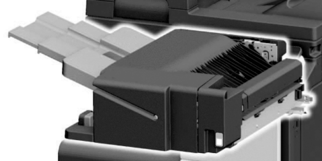
Fig. 1 Appearance of the new inner finisher FS-542
2
Experimental section
2-1. Product configuration of FS-542 and design issues
The new inner finisher, FS-542, is a strategic product that achieves both space saving and high functionality. It enhances customer value by automating the finishing process, enabling a smooth workflow and producing convenient, fast, and high-quality booklets. As one of its functions, a gripper mechanism (a mechanism that conveys a sheet bundle while gripping it) is employed to eject sheet bundles onto the stacking tray. By gripping and ejecting the aligned sheet bundle, the post-eject alignment is significantly improved (compared with the predecessor FS-533, the misalignment width, which was approximately 60 mm, was reduced to approximately one-tenth). This was achieved in a space-saving and low-cost manner.
Fig. 2 shows the finishing operation sequence of FS-542. As shown in Fig. 2(a)–(d), the sheets ejected from the MFP are received onto the processing tray and conveyed in a switchback motion (conveyance in the direction opposite to the normal sheet feed direction) by paddles (components that apply a frictional conveying force to the sheet using rotating elastic blades). The sheet edges are aligned by pushing them against the end fence. The edges orthogonal to the conveyance direction are also aligned by the side fences, aligning all four sides of the sheet bundle. This process is repeated for a specified number of sheets. If stapling is required in the selected mode, the stapler performs the stapling process to bind the bundle. As shown in Fig. 2(e)–(f), the sheet bundle is gripped and ejected toward the stacking tray. During this eject, mis-stacking of the sheet bundle on the stacking tray occurs. Fig. 3 shows details of this issue. When the gripper housing (the enclosure constituting the gripper mechanism) moves from the receiving position to the stacking position, the sheet bundle gripped by the gripper skews as the gripper housing skews. When the sheets are lowered from the processing tray to the stacking tray and pushed against the back plate, the sheets bend by a prescribed amount of skew on the rear side, generating a reaction force. Upon grip release, the sheet bundle is propelled, ultimately skewing significantly toward the front, causing mis-stacking.
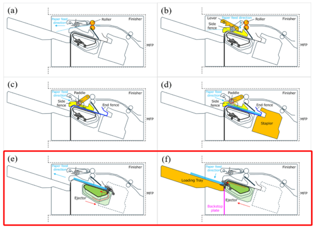
Fig. 2 Finisher operation sequence
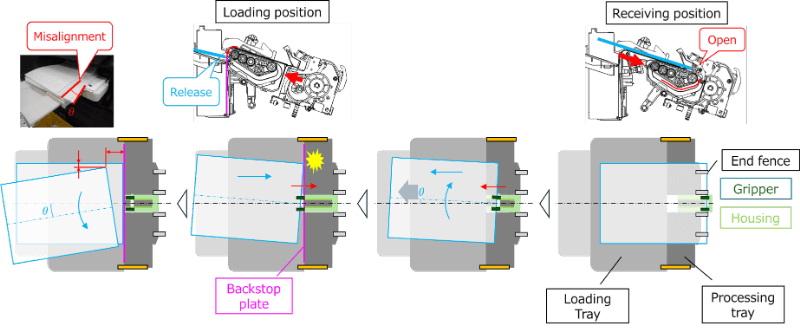
Fig. 3 Operational sequence and malfunction phenomena of the ejector unit
Fig. 4 shows the internal configuration of the gripper mechanism. Its first feature is the adoption of a housing-moving gripper ejection mechanism. It supports a minimum paper width of 90 mm and enables the conveyance of the sheet bundle across a full range using only a gripper. The second feature is that the moving mechanism is realized using a single motor (a one-side drive). These features enable space saving and cost reduction. However, owing to an imbalance in the drive load between the drive and non-drive sides, the gripper housing tends to skew during movement. Rack-and-pinion guidance and skew correction using a torsion bar (a rod-shaped elastic body) were implemented as countermeasures. With the conventional approach (multi-angle video recording within visible areas and inference of physical phenomena through visual inspection), transient changes in the sheet and mechanism behaviors cannot be sufficiently captured, resulting in ambiguous evaluation criteria and limitations. Therefore, using the video analysis method described in the following sections, we quantitatively characterized the sheet conveyance behavior and defined specific control values for transient states, enabling the evaluation of functional acceptability.
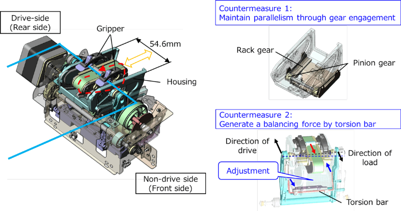
Fig. 4 Internal configuration of the ejector unit
2-2. Measurement system and imaging method
A high-speed camera is a general term used for imaging devices that capture high-speed phenomena that cannot be perceived by the human eye; these phenomena can then be visualized through slow-motion playback. The experimental setup used in this study is shown in Fig. 5. A visible-light high-speed camera (Photron FASTCAM Mini AX) and lighting equipment (Photron HVC-SL) were used as the imaging equipment, each fixed on a tripod. A high-speed camera was connected to a PC on which the bundled software (Photron FASTCAM Viewer) was installed. A reference scale (grid pattern) for calibration and color markers for tracking were applied to the mechanism components and sheets in the finisher, which were the imaging targets.
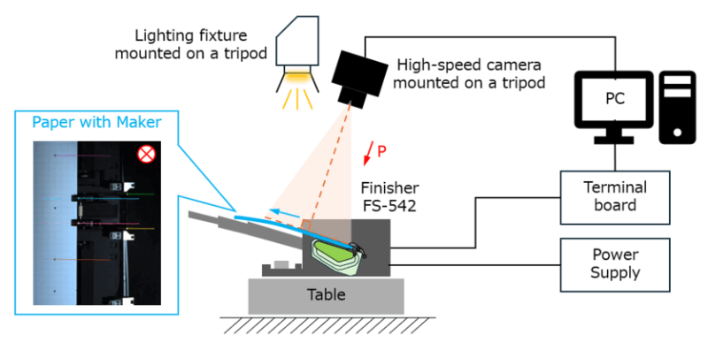
Fig. 5 Measurement system for paper feed dynamics
Regarding imaging settings, it was necessary to adjust the camera angle of view such that it was perpendicular to the target object to include the entire motion range of the tracking targets within the field of view, and to consider that shadows, reflections, and halation—depending on lighting—may cause loss of the color markers used for tracking.
Concerning software settings, the imaging speed was set to approximately 500–1000 fps. Assuming that the phenomenon of interest occurs within 0.01–0.02 s, the frame rate was set to values at least ten times higher. This established a practical margin according to the Nyquist sampling theorem.
The shutter was set such that the exposure time was half the duration of one frame, making the motion blur appear natural to the human eye.
A grid pattern of known dimensions was captured in the image for distortion correction. It was also used as a reference scale to determine image coordinates. Shading correction was applied to compensate for illumination nonuniformity (darkening toward the periphery compared with the center).
2-3. Video analysis method
Video analysis extends the visualization of high-speed motion captured by a high-speed camera for quantitative analysis.
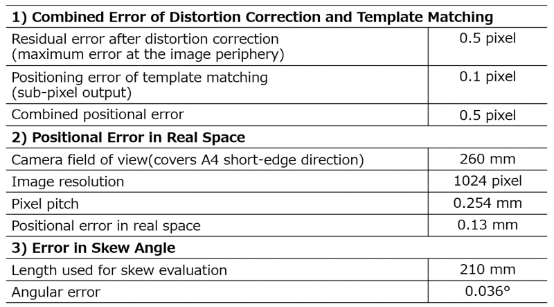
Motion can be quantified by obtaining the coordinate data of an object in an image and tracking it in each frame. In other words, the displacement, velocity, and acceleration can be calculated from the coordinate data and from the time difference between frames. Tracking based on template matching was used as the image analysis algorithm. In this method, the target object is specified and stored in advance, and the position with the highest similarity to the stored target is searched in each frame. Fig. 6 shows the overall procedure: (a) imaging settings and lens distortion calibration using a grid pattern; (b) specification of the reference image as the tracking target and the search region as that in which the same pattern as the reference image is searched on the initial screen; (c) execution of tracking (the target coordinates are automatically acquired by pattern matching within the search region in each frame); and (d) analysis by plotting graphs of the time-series coordinate changes. The open-source software Kinovea (v.0.9.5)3) was used for video analysis. The measurement accuracy of this method is listed in Table 1.
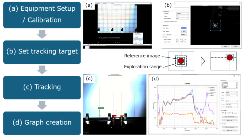
Fig. 6 Video analysis method
Table 1 Skew measurement accuracy
3
Results and discussion
3-1. Quantification of straightness and determination of set values for the skew correction mechanism
Fig. 7 shows the transient skew during gripper ejection. The difference in movement between the front and rear of the sheet bundle was converted into “skew,” which is easier to manage in an integrated manner. Here, “skew” refers to the angular error associated with the rotation of the conveyed sheet relative to the intended feed direction, and the leading, trailing, and side edges of the sheet are no longer parallel to the reference line. “Good straight-travel stability of the sheet bundle” was defined as the fundamental function. In other words, “small front–rear skew of the sheet bundle” was used as the evaluation criterion. Skewness was calculated using Eq. (1). where x and y denote the image positions of the marker in the current frame. The angle is calculated using the distance between the two points.
Fig. 7(a) shows the time-series changes in the skew of the gripper, housing, and conveyed sheets before implementing the countermeasures. If the skew exceeds the control value while placing the sheet bundle onto the stacking tray, as shown in Fig. 2(e) and (f), the skewed sheet catches on the upper part of the back plate. The decrease in the waveform exceeds the control value. In other words, the cases where the change in the angle from the initial angle exceeds the control value are treated as NG.
Fig. 7(b) presents the analysis results obtained after implementing the countermeasures. The variations are small over the entire operational range and skew is suppressed. Here, as a control factor, the spring force for skew correction of the mechanism described above was optimized.
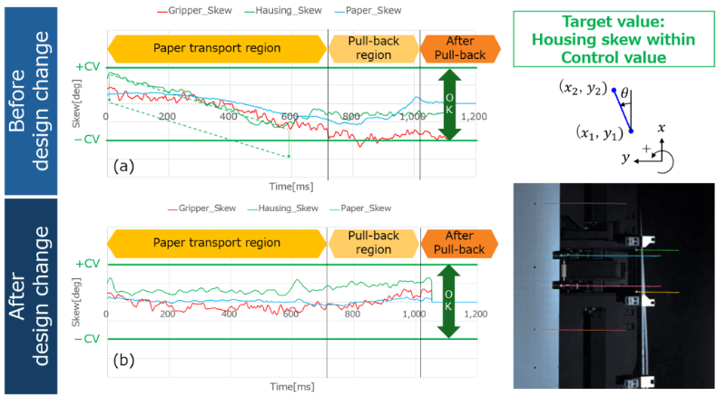
Fig. 7 Visualization of dynamic paper feed behavior

3-2. Quantification of inertial force and determination of the drive speed pattern
Fig. 8 shows a dynamic model of the gripper-holding section. Equation (2) shows the inertial force exerted on the sheet bundle during conveyance; Eq. (3) shows the holding force (friction force) of the pair of grippers; and Eq. (4) shows the critical condition under which the sheet bundle can maintain its held state during conveyance. The definitions and numerical values of each parameter are listed in Table 2. The torsion coil spring force for gripper holding was determined by considering straightness, as described in the previous section. In this section, we describe the identification of a velocity command pattern that satisfies the operational time constraint while maintaining the held state.
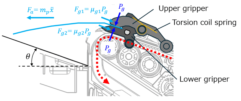
Fig. 8 Dynamic model of the gripper

Table 2 Parameters of the gripper
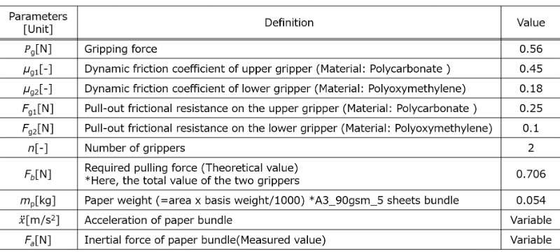
The inertial force Fa of the sheet bundle can be calculated using the acceleration measured by image analysis. Here, Fa is the force acting in the direction opposing the changes in the state of motion, and it increases substantially during sudden acceleration, deceleration, and vibration of the mechanism. The stability of the held state can be ensured by reducing variation. In accordance with Eq. (4), the circumferential speed command of the gripper is modified such that the inertial force does not exceed the gripper-holding force Fb. Fig. 9(a) shows the pre-countermeasure speed command pattern (dashed line), measured velocities of each marker, and estimated inertial force values. The inertial force waveform indicates increases at (1) the moment at which the gripper grips the sheet bundle, (2) the position where the belt tension applied to the housing is minimized, and (3) the moment when the gripper orbit switches from a straight path to a curved path. At these points, the critical condition of Eq. (4) is not satisfied. Therefore, as shown in Fig. 9(b), by revising the speed command pattern, the critical condition was satisfied over the entire operation range, thereby achieving stable maintenance of the held state. Although the sequence operation time increased, it was adjusted within the allowable range.
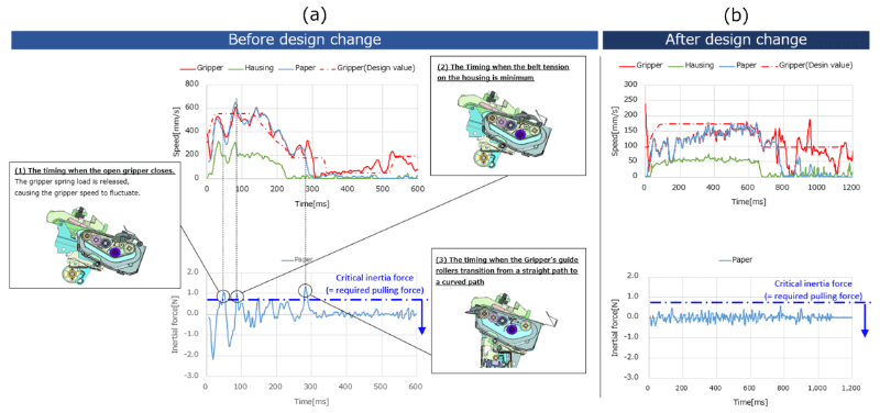
Fig. 9 Measurement and analysis of inertial force
3-3. Horizontal deployment to other functions
This evaluation method can be applied to other functions other than paper ejection. For example, evaluation of the alignment function is described here. The alignment function is given by the sequence shown in Fig. 2(c)–(d), in which the sheets are conveyed in a switchback motion and pushed against the end and side fences to align all four edges.
As shown in Fig. 10(a), when the side fence speed is high during switchback conveyance by the paddles, an impact-like contact occurs between the sheet and side fence, causing the sheet to flick away. Consequently, the skew cannot be fully corrected, and alignment deviation occurs.
Therefore, video analysis was performed to determine the optimal drive speed and operation timing. As a result, a smooth conveyance was possible without flicking the sheet away, as shown in Fig. 10 (b).
Fig. 10 Optimization of the driving speed of the side fence
3-4. Current status and outlook
By quantifying the sheet conveyance behavior by video analysis using a high-speed camera, specific control values for transient states can be defined and the acceptability of a function can be evaluated. In addition, by combining this approach with a dynamic model, the proposed method was found to be particularly effective during the parameter design phase for mechanical mechanisms and drive control. We plan to further refine this method and apply it as an evaluation technology for functional refinement in future product development.
4
Conclusion
In this study, we have contributed to improving the efficiency of product development by clearly defining fundamental functions, establishing evaluation technologies to measure them effectively, and reflecting the results in the design.
In future, we will examine advanced developments like compacting the evaluation process (simplifying procedures and equipment), establishing evaluation methods with expanded noise factors, and repurposing the method for evaluating other units.