1
Introduction
1-1. Overview
During an electrophotographic process, the toner image of a photoconductor is transferred onto the surface of the transported paper and fixed to the paper by heat and pressure during fusing. Therefore, paper characteristics significantly influence the paper-transport performance and process conditions for image formation, and fine control is achieved based on paper characteristic information. Accordingly, although implementation details differ among manufacturers, paper setting items related to “basis weight” and “paper type,” which are closely associated with paper characteristics, are provided and require customer setting operations. The basis weight is the most fundamental specification representing paper characteristics and is expressed as the weight per 1 m² of paper in units of g/m². Paper types are diverse, and papers used for electrophotography can be broadly classified into uncoated and coated. Uncoated paper corresponds to a paper type commonly used in offices (plain paper) and may be called lightweight paper, plain paper, heavyweight paper, recycled paper, or colored paper, depending on the basis weight. Coated paper is produced by resin-coating the surface of uncoated paper, resulting in a smooth, glossy surface. Depending on the gloss, coated paper can be classified into gloss paper and matte paper, which are the mainstream for catalogs and photograph collections.
1-2. Technology Development
1-2-1. Background for Technology Selection
In office printing, it is necessary to select MFP printing conditions based on the paper types linked to the basis weight table, such as lightweight paper, plain paper, heavyweight paper, recycled paper, colored paper, and envelopes. However, distinguishing paper types is challenging, and appropriate printing conditions may not be selected; in some cases, users are not aware that a selection operation is required. Our internal investigation reveals that 12.5% of the issues occurring in the market are related to incorrect paper settings.
To eliminate the need for paper selection operations, we developed a basis weight sensor and an envelope detection sensor. By automatically applying the detection results to the MFP-printing condition selection, the system reduces the operation time and mitigates jams and image defects caused by inappropriate paper settings.
1-2-2. List of Selected Technologies
The basis weight is a crucial parameter that represents the paper characteristics, and a basis weight sensor is widely used in office printing and production printing. We proposed an ultrasonic multifeed detection technology for envelope detection in an OP. This paper introduces a basis weight sensor, basis weight conversion, and a paper-type identification algorithm developed using core optical technologies developed by Konica Minolta.
2
Experimental section
2-1-1. Basis Weight Detection
When developing a sensor to measure the basis weight of paper, the measurements must be noncontact to avoid damaging the paper. Possible noncontact methods include the use of ultrasound or light transmittance; however, a comparison between the characteristics of the two methods showed that ultrasound is significantly influenced by humidity and temperature. Therefore, we adopted a measurement method based on light transmittance, which enables stable measurements.
2-1-1-1. Optical Basis Weight Detection
Specific wavelengths were found to be suitable for measuring the basis weight using light transmittance. Figure 1 shows the correlation between transmittance and basis weight at each wavelength for approximately 1,000 major paper types. In the visible-light range, when paper manufacturers or brands differ, the transmittance characteristics change owing to the components included to match the paper color, which reduces the correlation. In addition, the relationship between the transmittance and basis weight varies with the paper type. We attempted to address this issue by leveraging the difference in transmittance characteristics between the blue (B) and near-infrared (IR) wavelengths.
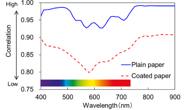
Figure 1. Correlation between transmittance and basis weight at each wavelength1).
2-1-2. Basis Weight Conversion
First-Generation Media Sensor System
Because the relationship between the transmittance and basis weight differs by paper type, an optimal basis weight conversion formula must be selected for each paper type. Figure 2 shows the paper-type characteristics. Coated paper tends to exhibit lower blue transmittance owing to the components applied to the surface and can be classified based on the difference between near-infrared and blue transmittance. In addition, recycled paper can be classified based on the fact that the reflected light, G, from the paper surface decreases owing to the inclusion of wastepaper components. The basis weight was calculated using these characteristics by selecting the optimal conversion formula according to the following procedure:
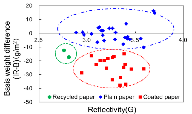
Figure 2. Classification of measured values of basis weights by paper type based on combinations of transmittance and reflectance of multiple wavelengths1,2).
First, in office printing:
Step 1: The recycled paper is identified from reflectance G.
Step 2: The coated paper and plain paper (uncoated paper) is identified from the basis weight difference IR–B, and the basis weight conversion formula is selected.
Next-Generation Media Sensor System
Because the relationship between the transmittance and basis weight differs by paper type, an optimal basis weight conversion formula must be selected for each paper type. The paper types were identified based on combinations of optical property judgments using transmitted and reflected light at wavelengths that depended on the paper characteristics. After identifying the paper type, we introduced an algorithm that calculated the basis weight for each paper type (Table 1). This enabled the basis weight detection for each paper type (Fig. 3). The transmitted and reflected light are detected using multiple light-emitting diodes (LEDs) arranged on opposite sides of the paper and a photodiode (PD). In addition, LEDs and PD were arranged to minimize detection variation owing to changes in the paper position, enabling stable paper detection during paper transport. Furthermore, improvements to the control algorithm enhanced the robustness against sensor contamination by paper dust, thereby increasing the sensor reliability.
Table 1. Example of a definition table for basis weight conversion formulas based on multiple optical property judgment results3).
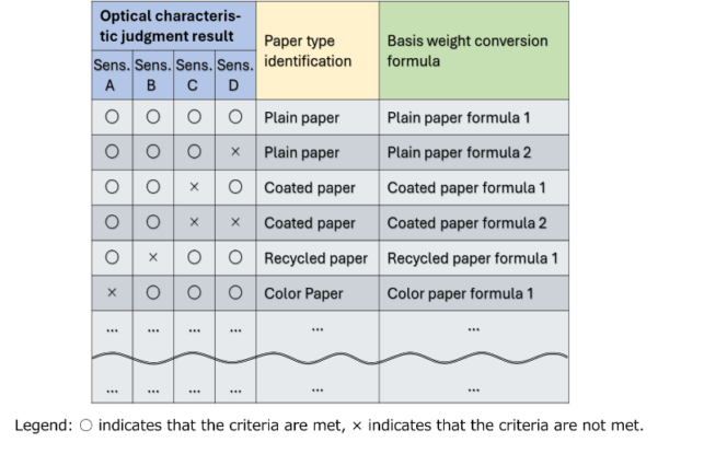
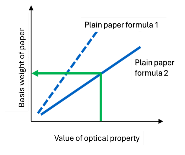
Figure 3. Example of basis weight definition from a conversion formula selected by the improved paper type identification algorithm3).
2-1-3. Basis Weight Sensor Configuration
Figure 4 shows the configuration of the basis weight sensor in the first-generation sensor system. Three types of LEDs were used in this study. The transmittance was calculated by detecting IR and B transmitted light using a PD placed on the opposite side of the paper. The reflectance was obtained by measuring the reflected light G from the paper surface. Six types of LEDs were used in the next-generation media sensor systems. The transmittance was calculated by detecting IR and B transmitted light using a PD placed on the opposite side of the paper. The reflectance was obtained by measuring the reflected IR, UV, V, and R light from the paper surface.
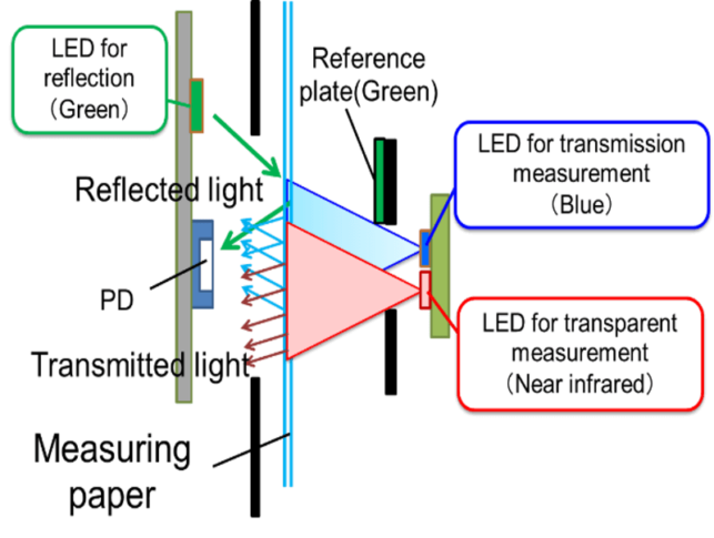
Figure 4. Basis weight sensing configuration of the first-generation media sensor system1,2).
2-1-4. Ultrasonic Sensor Configuration
Figure 5 illustrates the mechanism by which the machine automatically detects envelopes and applies the optimal printing settings to frequently used envelopes. Envelopes are detected based on the attenuation of ultrasound when it passes through an interface between media with different acoustic impedances. This enables the identification of the envelope media based on the intensity of the ultrasonic signal transmitted through the air layer of the envelope (an industry first). By enabling printing optimized for envelopes, the system reduces machine downtime associated with frequent envelope printing and improves operational productivity.
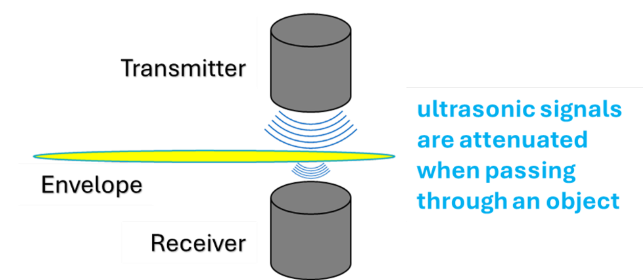
Figure 5. Diagram of ultrasonic sensor configuration for envelope identification3).
2-1-5. Circuit Configuration
First-Generation Media Sensor System
Figure 6 shows the circuit configuration for the optical basis weight detection. In the light-emitting circuit, the PWM duty is adjusted for each LED such that the received-light output becomes constant when there is no paper in the LED optical path. In the light-receiving circuit, the gain of the amplifier (AMP) is switched based on the presence or absence of paper, such that even when paper is present in the LED optical path and the received light decreases, the signal is amplified to a specified voltage and input into the basis weight calculation block. This mechanism enables the accurate measurements of paper transmittance and reflectance and improves the accuracy of the basis weight calculation.
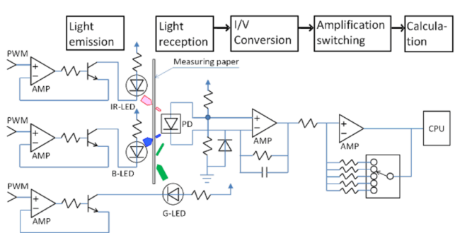
Figure 6. Detection circuit diagram implementing LED light intensity adjustment and light reception signal amplification switching1).
Next-Generation Media Sensor System
Figures 7 and 8 present the hardware configuration and control overview of the basis weight and ultrasonic sensors, respectively. First, for the basis weight sensor, the control CPU communicates an analog value to a D/A converter to set the gain, and a constant-current circuit switches and lights the LEDs based on the synchronization signal. The PD output value is then read according to the LED light intensity. In contrast, for the ultrasonic sensor, the control CPU transmits the ultrasound via an ultrasonic drive circuit through a synchronization generation circuit and reads the received value after amplifying the received ultrasonic signal using an amplifier circuit.
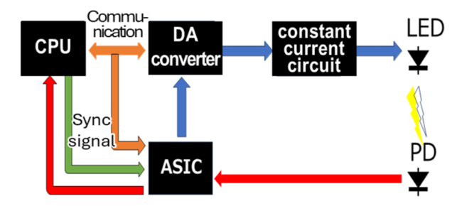
Figure 7. Optical sensing circuit diagram for basis weight determination applied to the next-generation media sensing system3).
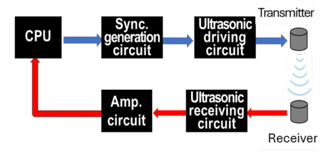
Figure 8. Ultrasonic sensing circuit diagram for envelope identification applied to the next-generation media sensing system3).
2-2. Implementation
2-2-1. Office Printing
Figure 9 shows the sensor implementation requirements. The requirements are as follows:
1) The papers fed from all paper feed ports (1, 2, 3, 4, and bypass ports) are identified.
2) Sensor data are acquired while the paper is being transported to prevent reduction in printing productivity.
However, the transport path is wide and the paper flutters, and the paper angle varies when passing through the sensor, depending on the feed port. Therefore, rollers were provided in the basis weight sensor section to narrow the transport path and stabilize the paper path and posture during transport. In addition, the basis weight sensor was placed above the center of the roller to reduce the angular difference at the sensor passage, reducing the angular variation at the detection position and improving the accuracy of paper identification.
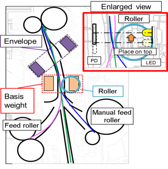
Figure 9. Placement of Basis weight sensing/ Envelope sensing / Rollers and transport guides in the paper transport path1).
Figure 10 shows the paper-setting screen for the paper-feed cassette. Automatic paper-type detection is enabled by default for each cassette, and the man–machine interface is designed to prevent setting errors by eliminating the need to intentionally select print conditions. Even when customers do not know the paper type, the information obtained by the automatic paper-type detection is reflected on the paper-setting screen, thereby eliminating the time required to investigate unknown papers. When manual settings are adopted, the media detection setting is automatically turned off and may be left off. Therefore, a function is provided that automatically turns the media detection setting back on when the paper feed tray is opened/closed or when there is no operation for a specific period. This helps to prevent paper jams and image quality degradation caused by paper-type setting errors.
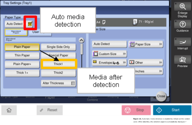
Figure 10. Automatic media detection is enabled by default on the control panel. After detection, the detected paper is automatically displayed1).
Figure 11 illustrates the response to refilling a paper-feed tray with different types of paper, which is common practice. Normally, media detection is performed, and the paper setting is applied to the first sheet after the paper is set in the bypass tray and to the first sheet after the paper feed tray is opened/closed. In addition, by acquiring data for each subsequently fed sheet with the media sensor, the system detects paper changes during tray refilling and automatically switches the paper settings. In the first step, the first sheet is detected as usual, and plain paper is identified. In the second step, a change in paper is detected. In the next task, media detection is executed, heavyweight paper is identified, and printing continues subsequently in the heavyweight paper mode.
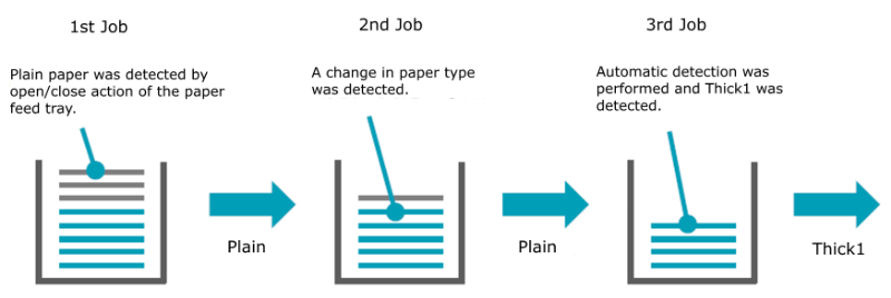
Figure 11. By scanning all subsequent sheets of paper,it detects changes in the paper type when refilling the tray and automatically switches the paper type.
3
Results and discussion
3-1. Market Data Analysis
Figure 12 shows the analysis results of the difference in the paper jam ratio (the market jam rate multiplied by a coefficient) caused by users’ incorrect paper selection settings when the media sensor function was ON versus OFF. The survey conditions correspond to those of first-generation media sensor systems. Based on statistical data for one year in the fiscal year 2022, paper jams during media detection were reduced by approximately half compared with cases of incorrect paper selection settings, indicating a contribution to reducing user downtime. In next-generation media sensor systems, a higher jam-reduction effect is expected owing to the expanded range of detectable paper types.
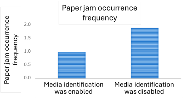
Figure 12. Comparison of the incidence of paper jams caused by incorrect paper type settings between models with equivalent specifications but equipped with a media sensor and conventional models without one (analysis results for the JP region in 2022)3).
4
Conclusion
The development of this product is expected to improve customer operability, reduce operational time, and minimize issues related to paper settings. In office printing, customer paper settings become unnecessary, reducing the operational time by more than 10 s compared with conventional operation, while enabling the identification of characteristics for various types of papers. The content introduced in this article is scheduled for implementation in the following products:
• OP inline type
Models equipped with the first-generation media sensor system
bizhub C750i / C650i / C550i / C450i
Intelligent Media Sensor IM-102
(Option for bizhub C360i / C300i / C250i)
• Models equipped with next-generation media sensor systems
bizhub C751i / C651i / C551i / C451i
Intelligent Media Sensor IM-103
(Option for bizhub C361i / C301i / C251i)
In the future, we will verify the effects of operability improvements by analyzing paper-type detection results collected from the above products in the market in association with internal product information and apply the findings to propose further workflow improvements for customers. We also aim to expand the supported paper types by advancing sensing technologies and revising estimation algorithms.